
"Wiring Micro Switch: A Complete Guide for Beginners"
Micro switches, renowned for their precise characteristics such as small contact gap, short actuation travel, and rapid on-off switching, have become indispensable control components in applications ranging from household appliances to industrial automation equipment. Wiring a micro switch is far more than a simple connection of wires—it is a systematic engineering task that integrates electrical principles, mechanical structure, and safety standards. Proper wiring ensures the switch operates at its rated performance (e.g., rated current and voltage), prevents increased contact resistance, insulation damage, or malfunction caused by improper connections, and ultimately guarantees stable equipment operation within specified vibration and shock resistance requirements.
I. Wiring Fundamentals: Understanding Core Contacts and Circuit Logic
The prerequisite for any wiring operation is accurately identifying the terminal definitions of a micro switch. A standard Single Pole Double Throw (SPDT) micro switch typically has three key terminals:
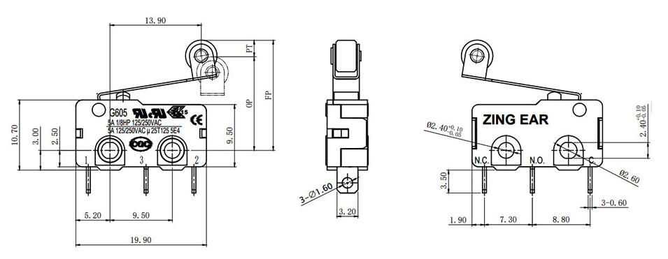
● Common Terminal (COM, Common): The dynamic reference point of the circuit, functioning as the "hub" of the current path.
● Normally Open Terminal (NO, Normally Open): In the unactuated (normal) state, this terminal is disconnected from the common terminal; when the switch is pressed or triggered, it connects to the common terminal.
● Normally Closed Terminal (NC, Normally Closed): Opposite in logic to the NO terminal, it is connected to the common terminal in the normal state and disconnects when the switch is actuated.
Correctly choosing between NO and NC determines the default state and control logic of the circuit, forming the foundation for diverse functions such as start-stop control, interlock safety, and status detection.
II. Advanced Wiring Methodology: Strategic Configurations Beyond Basic Connections
Depending on different control logic and system requirements, micro switch wiring can be strategically combined to achieve complex functionalities.
● Series Wiring: Constructing a Logical "AND" Gate for Enhanced Safety
1. Method and Purpose:
Connect the normally open (NO) or normally closed (NC) contacts of multiple micro switches in sequence along a main circuit path. The main circuit conducts only when all series-connected switches are simultaneously actuated (closed).
2. Circuit Logic Diagram:
Power L → [Switch A-NO] → [Switch B-NO] → Load → Power N.
3. In-Depth Application:
This method is widely used in high-safety scenarios. For example, on industrial machinery safety guards, two micro switches are installed at a distance and connected in series—only when both protective doors are fully closed (both switches actuated) can the equipment start, achieving physical dual interlocking and significantly enhancing operational safety. During wiring, ensure each switch’s load current remains within its rated capacity and that the total voltage drop meets system requirements.
● Parallel Wiring: Constructing a Logical "OR" Gate for Multi-Point Control
1. Method and Purpose:
Connect the NO contacts of multiple micro switches in parallel between the common terminal and the load. The circuit conducts when any one of the switches is actuated.
2. Circuit Logic Diagram:
Power L → COM, then COM → (connected simultaneously to [Switch A-NO], [Switch B-NO]), with all NO terminals converging → Load → Power N.
3. In-Depth Application:
Suitable for applications requiring convenient multi-point control. For instance, in large lighting systems, parallel micro switches can be placed at different room entrances to enable flexible control such as "one-button on, multi-point off," or vice versa. Note that while parallel wiring does not increase current per contact, the power supply must handle the total current that may result from simultaneous activation at multiple points.
● Cross (Composite) Wiring: Achieving State Interlocking and Mode Switching
1. Method and Purpose:
Utilize both NO and NC contacts of one or more micro switches in combination with other switches or components through cross-connection to form interlock circuits, bistable circuits, or signal switching circuits.
2. In-Depth Application:
This is key to implementing complex automatic control. For example, in an "Auto/Manual" mode switching circuit, the NO contact of a micro switch is connected to the automatic control signal loop, while the NC contact is connected to the manual control loop. When the switch is pressed to select "Auto" mode, the NO contact closes (activating the automatic loop), while the NC contact opens (cutting off the manual loop), preventing signal conflicts and ensuring clear, safe system logic.
III. Standardized Wiring Procedures and Key Considerations
A reliable wiring operation should follow the in-depth procedures below:
1. Preliminary planning and identification:
Read the technical specifications carefully, confirm the rated voltage, current, insulation resistance (usually required to be greater than 100M Ω), and withstand voltage value (such as AC1500V for 1 minute) of the switch. The first step to avoid wiring errors is to verify and mark the COM, NO, and NC terminals using the resistance range of a multimeter.
2. Safe power-off and preparation:
Ensure that the entire operation circuit is completely powered off. Select wires with appropriate cross-sectional area and current capacity, and prepare suitable crimping terminals or welding tools.
3. Wire handling and connection:
Peel off the appropriate length of wire ends, tin them or use wire clamps to ensure a secure connection. For terminals that require welding, the welding temperature and time should be strictly controlled to prevent high temperatures from causing deformation of plastic parts inside the switch, which can affect the operating characteristics. It is recommended to use resin fixation (plastic sealed terminal) technology, which fills resin fixation after wiring, effectively eliminating exposed live parts and significantly improving drip resistance and long-term reliability.
4. Circuit connection and inspection:
According to the designed series, parallel, or crossover logic, accurately connect the wires to the corresponding terminals. After completion, visually inspect all wiring for firmness and no looseness, and ensure that the exposed conductor parts are properly insulated.
5. Functional and safety testing:
First, conduct an on/off test, using a multimeter to verify whether the on/off status between NO/NC and COM before and after the switch is triggered meets expectations. Subsequently, a load test is conducted at a safe voltage, followed by a complete withstand voltage test and insulation resistance test to ensure compliance with safety standards.
IV. Integration of Green Manufacturing and Reliable Wiring: A ZINGEAR Case Study
Excellent wiring reliability not only relies on exquisite craftsmanship, but also stems from the design and material commitment of the product from the source. We practice the concept of green manufacturing, which is deeply reflected in the manufacturing and wiring compatibility of micro switches.
ZINGEAR's entire line of micro switch productsstrictly comply with RoHS (Directive on the Restriction of the Use of Certain Hazardous Substances in Electrical and Electronic Equipment) standards, eliminating the use of harmful substances such as lead, mercury, cadmium, etc. from the source. This means:
1. he responsibility towards operators and the environment:
In the recycling process after production, assembly, and even the end of the product lifecycle, the potential harm to personnel and the environment is greatly reduced, reflecting the firm commitment of the enterprise to sustainable development and environmental responsibility.
2. Improving long-term contact reliability:
Using environmentally friendly high-performance engineering plastics (such as PA66 reinforced materials) as insulation shells and bases not only has good flame retardancy and mechanical strength, but also its more stable chemical properties reduce the risk of corrosive substances precipitating due to material aging in humid and high-temperature environments. This precipitate may migrate to the contact area and combine with nitrogen oxides (NOx) generated by the arc to form nitric acid, which corrodes internal metal components and leads to abnormal increase in contact resistance or even operational failure. ZINGEAR's environmentally friendly material selection fundamentally mitigates the risk of such chemical corrosion.
3. Ensure the long-term stability of wiring terminals:
The terminal part adopts high-quality copper alloy coating that meets environmental protection requirements, which has better oxidation resistance and conductivity. Combining the resin fixation (plastic sealed terminal) process mentioned earlier, while achieving excellent anti drip performance (up to IP67 level), the encapsulation resin used is also environmentally friendly and non-toxic formula, ensuring that the wiring points remain stable in long-term use or harsh environments, and the insulation performance will not decrease due to material degradation.
Therefore, choosing a micro switch that complies with RoHS standards, uses environmentally friendly materials, and advanced packaging processes, such as ZINGEAR's product, has significance far beyond regulatory compliance. It extends the instantaneous reliability of wiring operations to the lasting safety and stability throughout the entire equipment lifecycle, and is a solid guarantee for achieving "green reliability" of electrical connections.
Conclusion: Wiring is not only technology, but also philosophy
The wiring of micro switches reflects the beauty of system design logic, the rigor of safety regulations, and the profound concern for sustainable development in modern manufacturing from a microscopic physical connection point. It not only connects circuits, but also functions and safety, present and future. By mastering its in-depth methodology and selecting components likeZINGEAR that integrate green genes into product details, engineers can build electronic systems that are both powerful, efficient, responsible, and sustainable.
Tags: wiring micro switch Micro switch replacement IP67 protection switch selection
Related Recommendations
-
Differentiated Competitiveness of 12 volt Micro Switch
2026-03-31 -
Can my brand logo be printed on the micro switch? ZINGEAR micro switch supports customization
2026-02-12 -
The differences between Micro Switch and Limit Switch
2026-02-12 -
Which brand of mouse micro switches is the best? Deep analysis and recommendation
2026-02-12 -
The Robust G9 Waterproof Micro Switch: Design, Applications and Manufacturing Excellence by ZING EAR
2026-01-13 -
G201 Sealed Micro Switch | ZING EAR China ODM & OEM Manufacturer
2026-01-13