

"Which Automotive Micro Switches Offer Built-in Resistors to Simplify External Circuitry?"
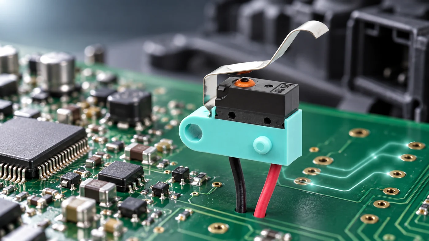
A switch in a detection circuit usually has a current-limiting resistor in series with it, placed on the board with its own footprint and tracks. Moving the resistor into the switch body removes the footprint, the tracks and one placement step, and it puts the resistor inside the same sealed enclosure as the contacts it protects. What the resistor protects, what the sealed body has to absorb once the resistor is inside, and which positions justify the integration are addressed below, with the ZINGEAR G306A as the worked example.
Short answer
Sealed micro switches with a resistor already inside are a narrow category. Omron publishes a resistor-integrated microswitch family, and ZINGEAR offers the G306A with and without the resistor. Most published part numbers cover the sealed switch and leave the resistor on your board, which is why the resistance value, its tolerance and its temperature coefficient are rarely on a public datasheet at all. The resistor inside does one of two jobs, and the two jobs are not interchangeable: limiting the current that passes through the contacts, or shifting the output voltage so an ECU can separate a closed contact from a cut wire. The sections below cover the current-limiting version, which is what removes a component and its tracks from the board. The diagnostic version is a different part with a different specification, and the difference is set out further down.
What the resistor is protecting
A contact rating describes the steady current, and it’s the inrush at make that wears the contact. Contact erosion happens in the milliseconds while the gap is closing and opening, not during the hours the circuit sits closed. A capacitive load, an LED indicator string or a long harness with distributed capacitance can draw a peak at make that’s several times the steady figure, and the contact sees that peak on every operation.
A resistor in series caps the peak. The steady current barely changes, but the energy dumped into the contact at make comes down, and the electrical life moves with it.
What that energy does is transfer metal. At make and at break the gap is narrow enough to strike a short arc, and the arc moves material from one contact face to the other. Enough operations and the faces no longer meet flat, contact resistance climbs, and the controller starts reading an intermittent state on a switch that is mechanically fine. Limiting the peak limits the arc energy, which is the only part of the process a series resistor can reach.
If the load is capacitive, the electrical life figure on the datasheet wasn’t measured on your circuit. Published electrical life comes from a resistive load at a stated current. Put the same part in front of a capacitor bank and the number no longer applies, which is why the resistor is in the circuit before anyone starts counting cycles.
What the sealed body has to absorb
A resistor inside a sealed body has nowhere to put its heat except the body itself. An external resistor sits on copper and uses the board as a heatsink. Once the resistor moves inside an IP67 enclosure, sealed to the degree IEC 60529 defines, the only path out is conduction through the housing, and the housing is a plastic body sized for a switch rather than for thermal management.
The housing sets a ceiling. A switch with the resistor inside is a detection part rather than a load-carrying one, because the sealed body limits how much the resistor can dissipate. A dissipation ceiling is why built-in resistor versions cluster at the low end of the current range, and why a supplier quoting one for a load-switching position is worth a second question.
Heat also reaches the contacts. The resistor and the contact set share one cavity, so whatever the resistor dissipates raises the temperature the contact material sits at. Ask for the electrical life with the resistor in circuit rather than for the bare switch figure.
What the resistance value has to hold
An external resistor can be swapped during debug, replaced at a revision, or changed on a second build. A resistor inside the switch can’t be reached, so changing the value means changing the part number and re-qualifying. Fixing the value inside the part moves it from a board decision to a specification decision, to be settled before samples.
Two figures decide whether the value holds:
Tolerance sets how much two parts from the same lot differ. If the reading circuit has a threshold window, the window has to accept the whole tolerance band, not the nominal value.
Temperature coefficient sets how far the value drifts across the operating range. Automotive positions run from -40°C to +85°C, and the drift across that span stacks on top of the tolerance. A window that fits at room temperature can fail at either end.
Ask for both, and ask for a measured resistance at both ends of the range rather than a calculated one.
Which positions justify the integration
Integration pays where the board is already full, the position is already sealed, and the part will run for years without being reworked. Each of those has to be true, and the last one carries the most weight, because the value can’t be changed afterwards.
The board argument is straightforward: one footprint, two tracks and one placement step come off the assembly. On a dense board near a connector, that space is often the constraint rather than the cost.
The sealing argument is stronger. If the position already needs an IP67 part, an external resistor still sits outside that protection, on a board that needs its own conformal coating or its own enclosure. Moving the resistor inside puts it behind the same seal as the contacts.
The harness argument runs the other way. An external resistor on the board leaves the run between switch and board carrying the unlimited inrush, while a resistor at the switch caps the current at the source. On a long run in a door or a tailgate, that’s the difference.
Integration doesn’t pay where the board has room, where the circuit is still being tuned, or where the same switch has to serve two variants with different loads.
Which version fits the position
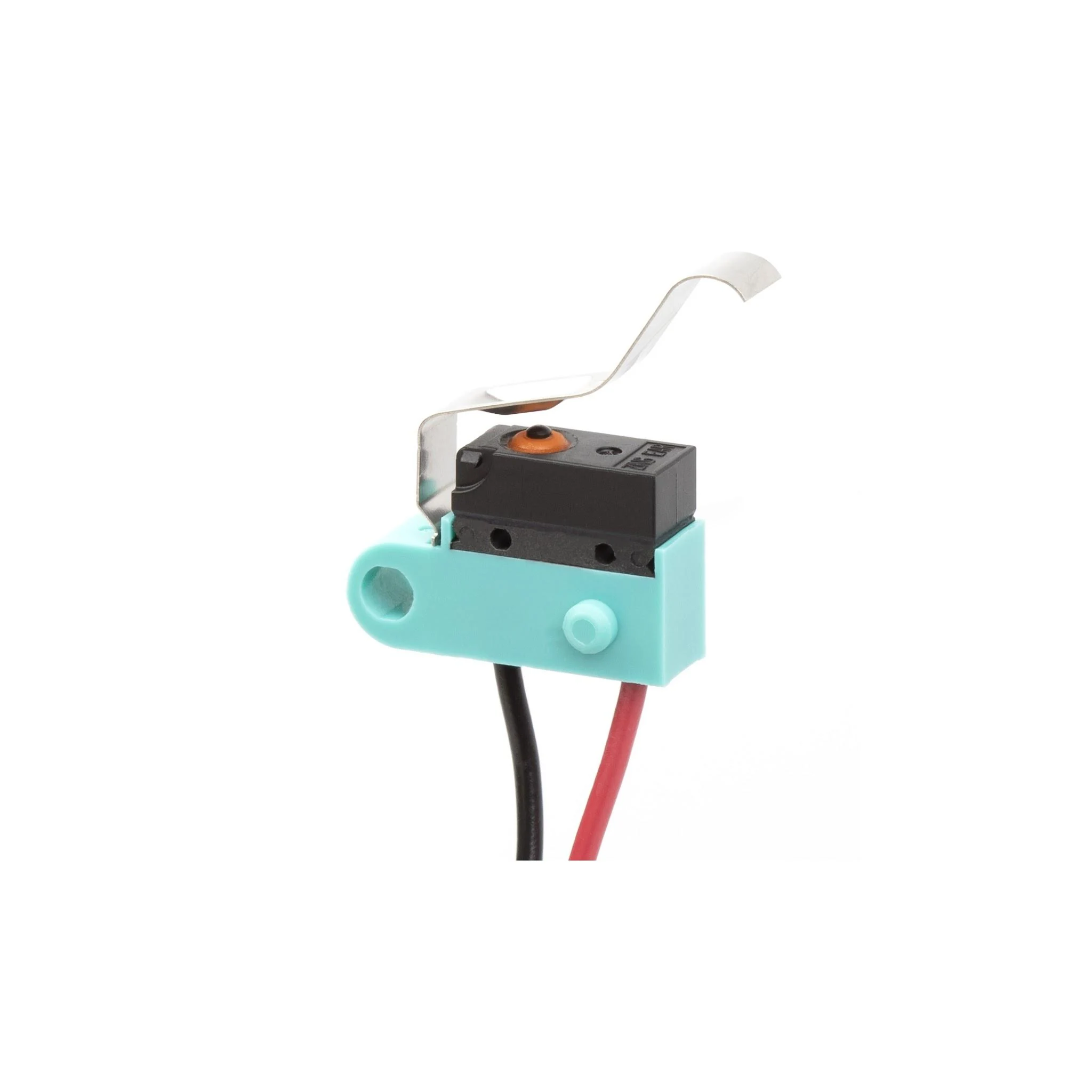
A position that needs the resistor gone from the board takes the current-limiting version, and a position that needs a cut wire caught takes the diagnostic one, which is a different part. ZINGEAR builds the current-limiting resistor into the switch body, which is what its configured micro switch development covers: the resistor is set as a parameter of the part rather than added to the customer’s board. The stated purpose is to simplify the external circuit and remove a placement step from assembly.
The ZINGEAR G306A is offered with and without the built-in resistor, so the same mechanical envelope covers both circuit designs. The part sits in the new energy micro switch range, which covers four positions:
- Charging gun insertion detection
- Storage cabinet interlocks
- Inverter status feedback
- Charging port lid detection Sealing is IP67 and the current rating runs from 3A to 15A, which places it in detection duty rather than load duty.
Life figures are generated in ZINGEAR’s own product laboratory: 300,000 mechanical cycles and 200,000 electrical cycles. For the conditions behind a specific figure, ask through the official website. The mechanical and electrical figures were both measured on the switch alone. A resistor sharing the cavity raises the temperature the contacts sit at, so the figure that describes a resistor version is the one measured on that version.
A built-in resistor is not a diagnostic resistor
Current-limiting and diagnostic versions are both sold as switches with a resistor inside, and each answers a different question.
A current-limiting resistor sits in series with the contacts and reduces the peak they carry. A limiting resistor changes how long the switch lasts, and tells the controller nothing new, because a closed contact and a cut wire still look the same from the input pin.
A diagnostic resistor changes the voltage the controller reads, so a closed contact, an open contact, a cut wire and a short each land in a different band. A diagnostic resistor changes what the controller can detect, and does not extend contact life.
The two can coexist in one part, and some suppliers build both a limiting element and a dividing element into the same body. A part carrying both is a third specification rather than a combination of the other two, and carries its own tolerance stack, because the diagnostic bands have to stay separated after the limiting element has taken its share of the voltage.
A position that needs fail-safe detection needs the diagnostic version, and asking for "a switch with a built-in resistor" won’t distinguish the two. Door latches, seatbelt buckles and hood detection are the positions where a broken wire has to be caught, and the specification for those starts from the voltage bands the ECU expects, not from the contact rating.
What to confirm before the board layout is fixed
| Item to confirm | Why it matters |
|---|---|
| Whether the resistor is current-limiting or diagnostic | The two carry different specifications and answer different requirements |
| Nominal value, tolerance and temperature coefficient | The value can’t be changed after the part number is fixed |
| Measured resistance at -40°C and +85°C | Calculated drift and measured drift are not the same evidence |
| Power the sealed body is rated to dissipate | Sets whether the position is detection duty or load duty |
| Electrical life measured with the resistor in circuit | The bare switch figure was measured on a different circuit |
| Whether the resistor and non-resistor versions share a footprint | Decides whether both can be carried on one board revision |
| Current rating at your operating voltage | A detection figure and a load figure are quoted differently |
| Lead exit direction and terminal type | The mechanical interface rarely transfers between sealed parts |
Send the list above to the ZINGEAR engineering team with the incumbent part number to have the resistor configuration and the sealing grade confirmed before pricing.
FAQ About Built-in Resistor Micro Switches
Which type of resistor is commonly used in automotive circuits?
Surface-mount thick-film resistors cover most of it, on the board rather than in the component. A switch with the resistor inside uses a chip resistor mounted on a small internal carrier, which is why the value is fixed at the part number rather than at the board.
Can a switch with a built-in resistor be used without the resistor?
Not on the same part number. Suppliers that offer both configurations, as with the G306A, carry them as separate part numbers sharing one mechanical envelope, so the decision is made at ordering rather than at assembly.
Does the resistor change the electrical life figure?
Yes, in both directions. The resistor lowers the peak the contacts carry, which extends life, and raises the temperature inside the body, which shortens life. So the figure has to come from a test with the resistor in circuit.
Can the resistance value be changed after sampling?
Changing it changes the part number, and a changed part number restarts qualification for an in-vehicle position. Settle the value, the tolerance and the temperature coefficient before samples are approved.
Which approvals should a resistor-integrated switch carry?
The same ones the position requires without the resistor. IATF 16949 for in-vehicle parts, and whichever safety mark the end product needs in its destination market. The resistor doesn’t add an approval requirement of its own.
How can I tell whether a supplier has run a position like mine before?
Published programme references are the closest thing to evidence. ZINGEAR publishes its by industry, with a charging port cover on BYD vehicles and a seat lock on the Mercedes C-Class under automotive industry solutions.
Sources
Standards and third-party datasheets
International Electrotechnical Commission. IEC 60529:1989+AMD1:1999+AMD2:2013, Degrees of protection provided by enclosures (IP Code). IEC Webstore:
https://webstore.iec.ch/publication/2452
International Automotive Task Force. IATF 16949:2016. Distributed by the Automotive Industry Action Group:
https://www.aiag.org/store/publications/details?ProductCode=IATF16949
Omron Corporation. Resistor-integrated Microswitch product page:
https://components.omron.com/us-en/products/switches/resistor-integrated-microswitch
All figures checked 15 September 2026.
Related Recommendations
-
ZINGEAR Micro Switch OEM Manufacturing Complete Guide
2026-07-23 -
ZINGEAR G306-150S150AA Automotive Micro Switch Officially Partners with Changan Automobile to Enable Precise Control of Sun Visors and Vanity Mirrors
2026-08-07 -
ZINGEAR G304 Micro Switch Debuts in Rail Transit Sector, Enabling Precise Sensing and Reliable Control for High-Speed Train Lifting Doors
2026-08-13 -
ZINGEAR G306-150E65BA-400 Electric Motorcycle Handbrake Micro Switch | Dreame Shouqu Certified Sensing Switch
2026-08-18 -
ZINGEAR G304 Micro Switch Supports Electric Two-Wheeler Electronic Lock Systems, Empowering Smart Lock Security and Durability Upgrade
2026-08-21 -
zingear Micro Switch Solution for Communication Base Station Equipment Status Detection — Building a Solid Safety Line for Long-term Stable Operation of Base Stations
2026-08-11 -
Electrolux Range Hood Switch Solution — Zing EAR: Solve Extreme Kitchen Reliability with Precision Sensing
2026-08-25 -
How can I replace the push-button switch on my range hood?
2026-08-27