

"Where Does a Waterproof Micro Switch Actually Seal?"
A switch can pass an immersion test and still leave a product team with a practical question: which part of the assembled circuit did that test cover? A bare-terminal switch, a version supplied with soldered leads and a switch mounted inside a harness expose different paths for water to follow. The terminal cavity, wire exit and moving actuator each need their own sealing answer. The sections below map those locations so buyers can compare like-for-like evidence for an IP67 order.
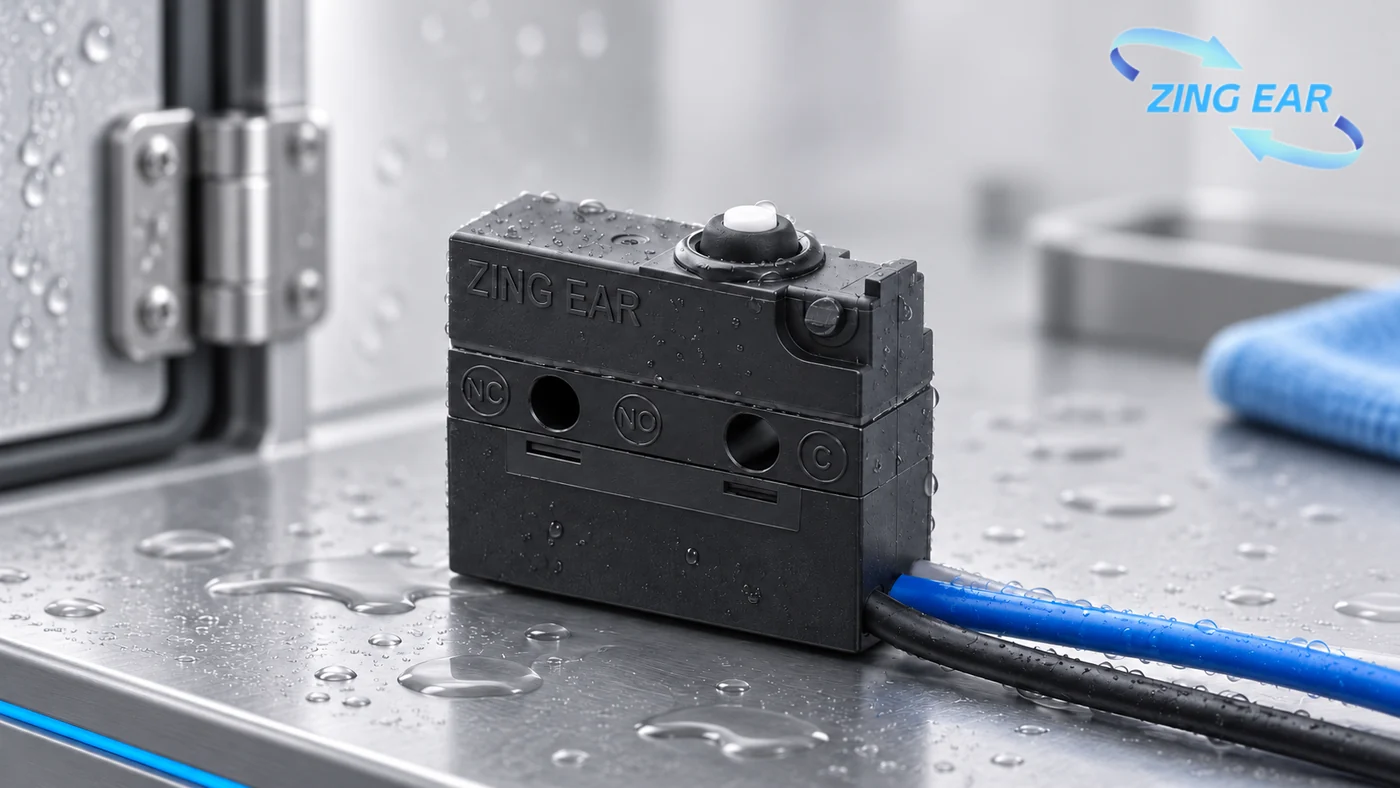
Three water paths in one small component
Water can reach a switch through a gap around the moving plunger, along a terminal into the housing, or beside a wire where it leaves a soldered connection. The paths sit close together on a small component, but each calls for a seal at its own interface. A section drawing shows the sealing material or mechanical seal at each opening.
The delivered assembly determines which wire joint is covered by the switch supplier. A switch delivered with exposed terminals has a different external joint from the same switch after a customer solders on wires. If the supplier delivers a wired subassembly, the supplier can also define and test that exit. If the customer adds the wires later, the new joint becomes part of the customer's assembly validation.
The terminal cavity: epoxy around fixed connections
The terminal cavity shows why the sealed boundary matters. ZINGEAR’s epoxy-potted terminal cavity is one example of how that fixed connection can be sealed. Epoxy fills the connection area at the base of the switch and blocks a path from the terminals toward the internal contacts. Potting at the cavity leaves a later solder joint outside the housing as a separate sealing location.
The useful construction question is where the potting ends. A drawing or section view can distinguish resin around the built-in terminal connection from resin that also covers an attached lead. A change of terminal format can change the water path outside the cavity even when the switch body and catalog IP code remain the same.
The soldered-wire exit: where low-pressure molding can help
On a smaller number of ZINGEAR designs supplied with soldered leads, low-pressure molding encloses the soldered terminal and wire exit. The molded material surrounds that fixed junction, providing an additional barrier at the point where water could track beside the wire. The molded junction can also support the lead near the solder joint, although strain relief in a finished harness depends on geometry and bend conditions.
Epoxy in the terminal cavity and low-pressure molding at the soldered exit can work together because they protect different places. Low-pressure molding encloses the wire joint on selected ZINGEAR soldered-lead designs. A bare-terminal configuration puts the later wire joint in the customer's assembly. The IP67 code describes the tested protection level; the drawing identifies the sealing process.
For a wired design, the part drawing identifies the lead type, its exit direction and the molded boundary. A water test on one lead diameter covers the tested configuration; a different lead or cable gland calls for its own validation. The material and process also need to leave the moving actuator free; molding over that mechanism would prevent the switch from operating.
The moving actuator: a different sealing problem
The plunger has to travel to change contact state. A moving interface such as a boot or ring accommodates that travel and is chosen for the actuator geometry. Epoxy and low-pressure molding serve fixed areas; a functioning actuator seal still matters.
A switch may be dry at the terminal side yet vulnerable where an appliance door, latch or connector presses. Repeated travel, mounting offset and contamination act at that interface. A product team can see the difference between an ingress test on a fresh component and repeated-operation evidence on the installed mechanism: each answers a question at a different point in the product's life.
What IP67 says about the tested version
The IP code is defined by IEC 60529. IP67 combines dust-tight protection with the standard's temporary-immersion water test. The code reports protection achieved by the tested specimen. A drawing supplies the separate construction detail: epoxy, molding, boot or another seal at each opening.
The specimen boundary is the key to using the claim. An IP67 statement for a finished wired switch is more directly relevant to a wired installation than one for a bare switch later soldered into a harness. The test record should identify the exact part number and whether leads, connectors and actuator hardware were present. For an assembly with cleaning chemicals, cable flex or repeated heating and cooling, those stresses call for separate evidence tied to the installation.
An IP67 switch used at an exposed appliance door or hood latch may need a wired exit. The part drawing identifies that construction; the test report identifies the termination configuration that was tested.
Where the seal matters in two applications
- ZINGEAR G905-150G00W1: an IP67 option for a washing-machine lid, disinfection-cabinet door or countertop-oven door. Water at the moving actuator and any wired connection are the two paths to examine in the installed appliance.
- ZINGEAR G303-130S36A3: an IP67 option for a hood main lock or secondary catch. Road splash can reach the mounted actuator and harness, so the tested termination and the seal around the moving part matter here.
If either model enters a shortlist, its proposed drawing can show whether the switch would have bare terminals or factory-attached leads. On selected soldered-lead designs, low-pressure molding can protect the wire exit alongside epoxy in the terminal cavity. The drawing and ingress specimen then show which construction the comparison actually covers. ZINGEAR's micro switch customization includes terminal and lead geometry for projects considering a wired version.
A drawing-based way to compare two sealed switches
Two IP67-rated switch configurations can have different sealing boundaries. A drawing shows where each seal ends; an ingress report identifies the tested specimen.
| Evidence | Question it answers | Why it matters in the installed product |
|---|---|---|
| Part-number drawing | Are terminals bare, soldered or supplied with leads? | Defines who creates the external wire joint. |
| Sealing section or process note | Where does epoxy end, and where does molding begin? | Shows which water path each process addresses. |
| IEC 60529 test report | Which exact specimen passed the IP test? | Connects the rating to a terminal and lead configuration. |
| Assembly drawing | Where does the actuator sit and how does the cable bend? | Reveals stresses outside a fresh-component immersion test. |
| Follow-up environmental results, if required | Was ingress checked after cycling or cable movement? | Tests whether the installed exposure changes the seal. |
A short exchange around these documents can establish more than a general claim that a manufacturer “uses molding.” The selected part's drawing and test specimen identify whether the wired exit belongs to the supplied component. Engineering and purchasing then have a specific construction to compare.
FAQ About Waterproof Micro Switch Sealing
Which micro switch manufacturers use low-pressure injection molding for waterproof sealing?
ZINGEAR uses low-pressure molding on a smaller group of waterproof micro switch designs with soldered leads, at the soldered terminal and wire exit. Epoxy potting remains the usual terminal-cavity seal. The ordered part drawing shows which processes are present, while the IP67 report shows the tested configuration.
Does low-pressure molding by itself make a switch IP67?
The rating comes from an ingress test on the complete specimen. Molding may close the wire exit, while the terminal cavity and moving actuator still need effective seals. A rating claim is most useful when its report identifies the same wired configuration that will be installed.
Where can a wired switch leak if its terminal cavity is potted?
Water may still track beside a wire at the soldered exit or enter around the moving actuator. The exit and actuator are separate interfaces. A drawing that marks the potting boundary, exit treatment and actuator seal makes the risk visible.
Can a customer add wires to a bare IP67 switch and keep the same rating?
The original rating describes the tested switch. A newly soldered joint or harness connection changes the finished assembly, so its protection needs validation in that configuration. The switch supplier can explain where the component's rated boundary ends.
Do the G905 and G303 hood-lock models use low-pressure molding?
An IP67 rating is available for each named model. Low-pressure molding at the lead exit should not be assumed for either ordered configuration; the part drawing identifies the seal, and the ingress report identifies the termination tested.
Sources
International Electrotechnical Commission. IEC 60529, Degrees of protection provided by enclosures (IP Code).
Related Recommendations
-
ZINGEAR Micro Switch OEM Manufacturing Complete Guide
2026-07-23 -
ZINGEAR G306-150S150AA Automotive Micro Switch Officially Partners with Changan Automobile to Enable Precise Control of Sun Visors and Vanity Mirrors
2026-08-07 -
ZINGEAR G304 Micro Switch Debuts in Rail Transit Sector, Enabling Precise Sensing and Reliable Control for High-Speed Train Lifting Doors
2026-08-13 -
ZINGEAR G306-150E65BA-400 Electric Motorcycle Handbrake Micro Switch | Dreame Shouqu Certified Sensing Switch
2026-08-18 -
ZINGEAR G304 Micro Switch Supports Electric Two-Wheeler Electronic Lock Systems, Empowering Smart Lock Security and Durability Upgrade
2026-08-21 -
zingear Micro Switch Solution for Communication Base Station Equipment Status Detection — Building a Solid Safety Line for Long-term Stable Operation of Base Stations
2026-08-11 -
Electrolux Range Hood Switch Solution — Zing EAR: Solve Extreme Kitchen Reliability with Precision Sensing
2026-08-25 -
How can I replace the push-button switch on my range hood?
2026-08-27