

"EV Charging Micro Switches for Connector Presence and Lock Feedback"
Inside a charging gun, an insertion detector and an electronic-lock detector can look like the same small switch. The insertion switch changes contact state during connector insertion; the lock switch changes state as the lock moves. The controller reads those transitions as connector and lock feedback. A charger that reads the signals incorrectly can refuse a valid connection or treat an incomplete one as ready.
The switch earns its place in the design when its signal changes at the right point in the actual connector. The article below explains connector and lock feedback so a charging-equipment team can choose a suitable switch and verify its signal in the assembled gun.
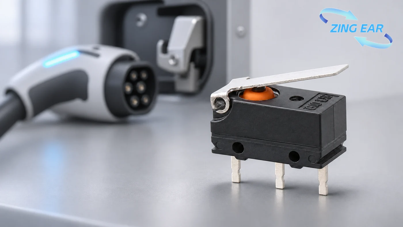
What do the two switch signals mean?
The connector's mechanical path determines where a switch sits. The controller then interprets that switch as a particular state. A useful supplier recommendation starts with that state, because a connector-presence signal and a lock-position signal can fail in different ways.
| Position in the charging assembly | Question the controller needs answered | What can go wrong at the switch | What the mounted sample reveals |
|---|---|---|---|
| Connector presence | Has the plug reached the intended engagement position? | A late or early change of contact state can misreport partial insertion | The contact transition across the actual insertion travel |
| Electronic-lock feedback | Did the lock reach its intended position? | A switch can change state while the latch is still short of its stop | Whether electrical feedback agrees with the latch's measured position |
For a presence detector, the critical observation is the moment the connector state changes during insertion and withdrawal. If the switch trips before the connector reaches the intended position, the controller needs another way to distinguish partial engagement. A switch with the right catalog dimensions can still change state at the wrong point once installed behind the charging-gun shell.
Lock feedback concerns a separate motion. The lock command tells the mechanism to move; the feedback contact changes state when the latch presses the switch actuator. The controller can interpret that transition as “locked” after it has been matched to the physical latch position, including a latch that stops partway. The assembled-connector test compares the signal with the latch position. The switch supplier can describe the switch's travel and contact behavior; the connector designer knows where the latch meets the switch actuator.
Starting candidates for charging-gun feedback
For example, ZINGEAR offers both plain-contact and resistor-integrated switches for charging-gun feedback. The controller input and available space inside the connector guide the choice.
ZINGEAR G10B03-150P03A
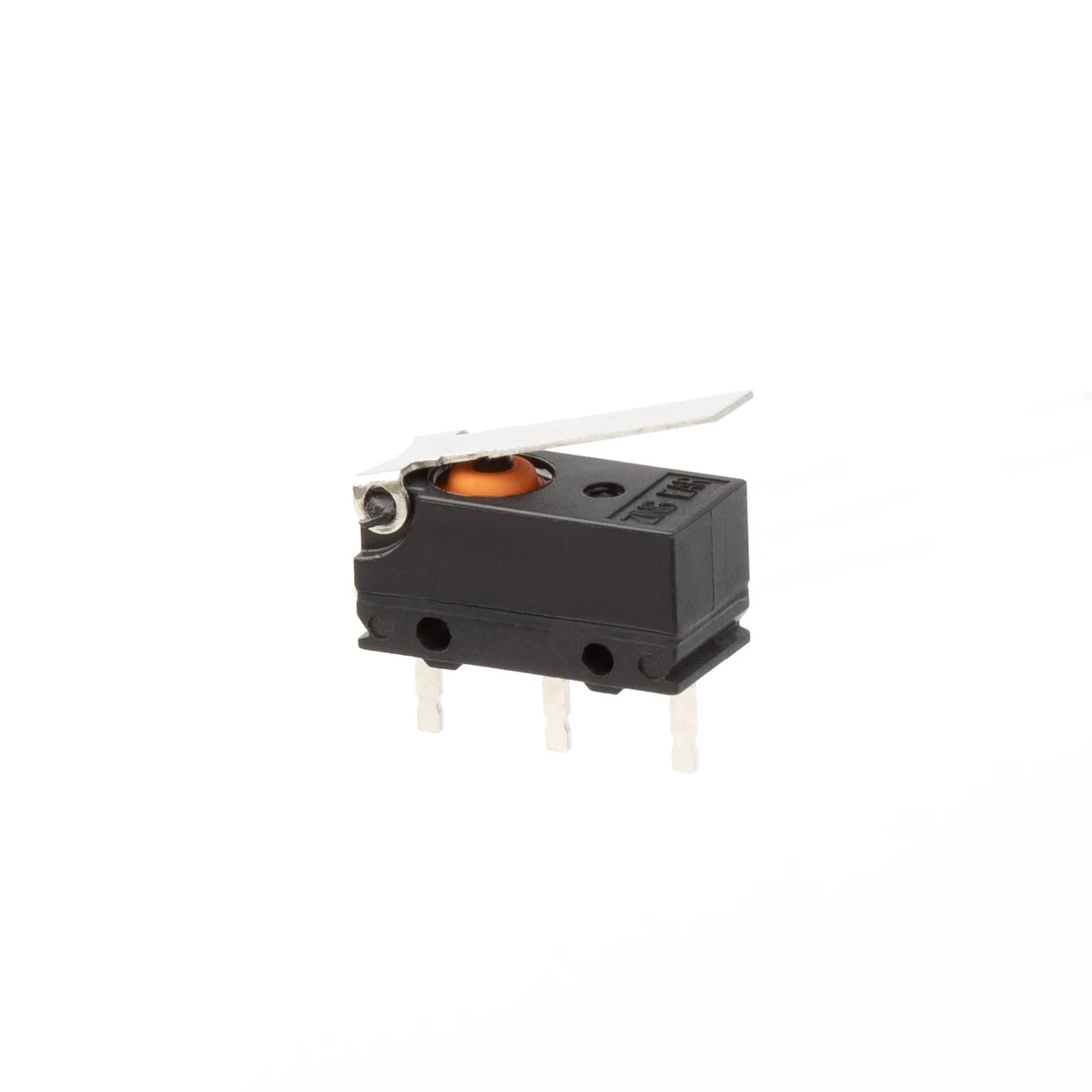
- Electrical form: Single-pole, double-throw (SPDT) contacts with common (COM), normally open (NO), and normally closed (NC) terminals. The controller can monitor the contact state that matches its insertion or lock logic.
- Environment: IP67 dust-and-water rating under IEC 60529; specified operating temperature from -40°C to +85°C.
- Where it helps: Its compact body fits a tight charging-gun cavity. The mounted actuator still needs to change state at the connector's intended engagement point.
ZINGEAR G306A-150P03A3B-A002
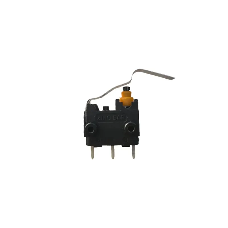
- Contact form: One normally closed (NC) and one normally open (NO) contact give the connector circuit a choice of which state to monitor.
- Electrical rating: This A002 configuration is specified at 15 A and 250 V. In a charging gun, the contact usually operates in a low-current sensing circuit, so its behavior is checked at the controller input's actual voltage and current.
- Built-in feature: A resistor sits inside the switch, reducing the need for an external resistor at that position.
- Circuit choice: ZINGEAR offers current-limiting and diagnostic G306A configurations. The diagnostic configuration can help the controller identify a broken or shorted wire when its resistor network and input thresholds are matched.
- Environment: IP67 rating for the named model. The selected terminal and lead arrangement determines what the ingress test covers.
- Operating temperature: The G306A series range is -40°C to +85°C. The selected A002 build's drawing establishes the temperature limit used for a finished connector design.
- Endurance: Mechanical life describes repeated actuation; electrical life also depends on the switched circuit. For the selected A002 build, the relevant life result needs its own test conditions and the connector's actual input and insertion cycle.
The connector design gives each model its job. A plain contact input can use the G10B03 candidate; a controller designed around a resistor network may need the G306A route. The schematic and measured input levels settle that electrical choice. An engineer can start with an early mechanism sketch or an existing connector design and discuss it through the new-energy micro switch range.
What does IP67 cover for a switch inside a charging gun?
ZINGEAR's charging-gun candidates carry IP67 ratings. The classification concerns dust and water ingress at the tested part boundary, under the conditions behind the rating. The finished charging gun has additional paths at its shell joint, cable exit and moving mechanism. A sealed switch helps protect the sensing element; the assembled connector test shows how its mounting and cable routing perform together.
The test version matters here. Bare terminals, soldered leads and a finished wire exit expose different surfaces to water. The offered drawing and ingress-test configuration identify which surfaces the IP67 result covered. A connector exposed to cable flexing and repeated insertion also needs its signal checked after those motions. The IP67 micro switch guide explains why the body, terminal and lead exit can carry different coverage.
How a sample turns a candidate into a design decision
A useful sample test follows the connector through its real motion. The team records the mechanical position and controller input together, then repeats the movement at the mounting-tolerance extremes. Recording both values shows whether a proposed switching point has room for normal production variation.
Partial engagement deserves its own observation. The connector may meet the switch actuator before every other interface reaches its final position. Reading the controller input throughout insertion captures that intermediate state along with both endpoints. For a lock-feedback switch, a stalled latch can create a similar gap between the commanded and reached position.
The electrical test then uses the actual controller input. A low-current sensing circuit is assessed at its own voltage and current; a switch that interrupts a load needs results for that load instead. Where a diagnostic resistor version is proposed, open-wire and short-circuit simulations show what the controller actually reports. The same trial establishes the exact resistor version, its wiring and the controller's input thresholds as concrete engineering values.
| Design question | Evidence that answers it | Decision it changes |
|---|---|---|
| Does the actuator trip at the right point? | Installed travel plot or measured position at each contact change | Keep the actuator, adjust it or move the mounting point |
| Does the controller read every intended state? | Contact-state trace at the real input current; fault injection for a diagnostic circuit | Choose a plain-contact or diagnostic version |
| Does sealing survive this assembly? | Part-specific ingress result plus assembled connector exposure test | Select the lead exit and any additional housing seal |
| Will the approved part match production? | Full part number, drawing revision and sample identity | Freeze the tested configuration for the next production build |
Sample evidence can be built around an existing connector drawing, but a project can also begin before a complete request for quotation exists. Configured micro switch development covers travel, operating force, terminals and lead exit. An early discussion can begin with the space, the movement to be detected and the controller signal; the proposed version and its verification work follow from those facts.
FAQ About EV Charging Micro Switch Suppliers
Can you recommend a supplier for an EV charging-gun micro switch?
ZINGEAR offers the G10B03 for connector-presence and lock-position feedback, with the G306A available for a resistor-integrated circuit. The two options serve different signal paths; the selected version can be evaluated in the charger's assembled connector.
Is the charging-gun switch the component that carries charging current?
In the positions described here, the controller reads the switch contact state to determine presence or lock state. The connector's power path is a different part of the design. If a proposed switch actually interrupts a load, its rating and test must cover that specific circuit.
When does a built-in resistor help with lock feedback?
A built-in resistor helps when the controller is designed to interpret its electrical effect. A diagnostic circuit can make a wiring fault distinguishable from an ordinary lock state if its resistor network and input thresholds are set for that purpose. A current-limiting version serves a different circuit job, so the two versions are identified separately in a proposal.
Can one switch model serve insertion sensing and lock feedback?
The same family may be considered for both. Each mounting position still has its own actuation travel, contact state and failure behavior. A mounted sample in each position shows whether the proposed version reaches the intended state at the right moment.
What should an EV charging equipment buyer see first from a candidate supplier?
The named model's drawing and circuit description give the quickest useful start. From there, the supplier and equipment team can connect the actuation point, electrical duty, sealing configuration and available test results to the actual connector position. A quotation becomes more meaningful once the candidate version has been identified.
Sources
Related Recommendations
-
ZINGEAR Micro Switch OEM Manufacturing Complete Guide
2026-07-23 -
ZINGEAR G306-150S150AA Automotive Micro Switch Officially Partners with Changan Automobile to Enable Precise Control of Sun Visors and Vanity Mirrors
2026-08-07 -
ZINGEAR G304 Micro Switch Debuts in Rail Transit Sector, Enabling Precise Sensing and Reliable Control for High-Speed Train Lifting Doors
2026-08-13 -
ZINGEAR G306-150E65BA-400 Electric Motorcycle Handbrake Micro Switch | Dreame Shouqu Certified Sensing Switch
2026-08-18 -
ZINGEAR G304 Micro Switch Supports Electric Two-Wheeler Electronic Lock Systems, Empowering Smart Lock Security and Durability Upgrade
2026-08-21 -
zingear Micro Switch Solution for Communication Base Station Equipment Status Detection — Building a Solid Safety Line for Long-term Stable Operation of Base Stations
2026-08-11 -
Electrolux Range Hood Switch Solution — Zing EAR: Solve Extreme Kitchen Reliability with Precision Sensing
2026-08-25 -
How can I replace the push-button switch on my range hood?
2026-08-27