

"Sourcing Door-Ajar and Hood Position Micro Switches for US Vehicles"
The US door-lock and retention standard, FMVSS No. 206, was updated by NHTSA in February 2007. Its current requirements apply to specified vehicle door systems, including latch and retention behavior and certain warning provisions; the vehicle program evaluates the door switch within that system, while hood sensing follows its own program requirements. A door-ajar signal can miss the secondary-latch state when the cam stays short of the switch's operating point.
A door-state map anchors the discussion below and helps OEM and Tier 1 buyers assess a switch in the assembled latch.
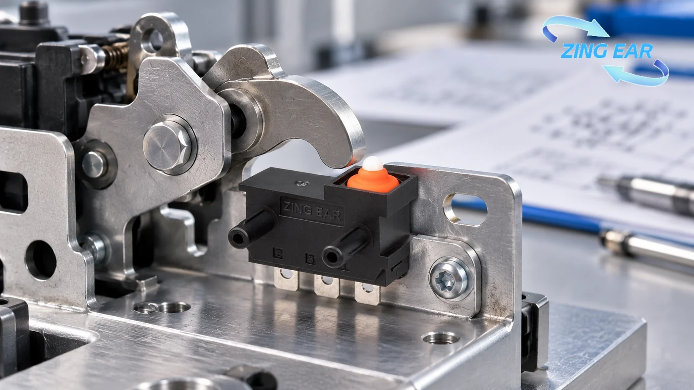
Start with the actual latch states
Door sourcing starts with a mechanical truth table. The door-state map distinguishes open, secondary-latched and fully latched positions. At each point, cam position, actuator travel, contact state and controller response show whether one switch can convey the required information. A single switch transition can report “fully latched” versus “not fully latched”; distinguishing an open door from a secondary-latched one requires an additional signal or mechanical logic.
Apply FMVSS 206 to the door system
FMVSS No. 206 sets door-lock and retention requirements for specified vehicle and door configurations. For some rear-hinged and sliding doors, its warning provisions also affect the signal the vehicle must produce. The OEM can use the applicable door provision to define the latch states, sensor position and dashboard response for its program.
The NHTSA laboratory procedure describes physical latch and retention tests. The eCFR text supplies the legal requirements; NHTSA labels its laboratory procedure as a testing guide rather than an official interpretation. The electrical state is evaluated within the vehicle design alongside the rule's physical latch, hinge, load and inertia requirements.
Build a door-state and fault matrix
The controller specification should state whether an open door and a secondary-latched door share one signal or require separate states. The controller specification should also define how wiring faults appear to diagnostics under the vehicle program’s applicable requirements.
| Physical or electrical condition | What a single full-latch switch may report | What to check in the latch and controller | Procurement evidence |
|---|---|---|---|
| Door open | Not fully latched | Correct state through the full cam travel | Actuation-point drawing and contact-state record |
| Secondary latch | Often still not fully latched | Whether the controller must distinguish this from open | Cam/switch truth table across tolerance extremes |
| Fully latched | Fully latched | Stable state after slam, gentle closure, and vibration | Force, travel, differential and endurance test |
| Open circuit | May imitate an open contact | Fault detection and fail behavior for the chosen normally-open/closed circuit | Harness fault-injection result |
| Short to ground or supply | May imitate a valid state | Diagnostic separation from legitimate latch position | Circuit schematic and fault-state test |
| Contact bounce or moisture leakage | Intermittent transitions | Filter timing, input wetting current, environmental margin | Contact and post-conditioning signal traces |
Choose a candidate by geometry and circuit
The switch has to change state at the right point in the actual latch. Buyers need its contact form, controller current, operating force and travel range. The latch drawing shows where the cam meets the actuator; tests cover the lead exit, water exposure, vibration and expected operations. At a low-current controller input, stable contact behavior at the actual wetting current matters more than a high switching-current label.
The published automotive model can be screened against the latch drawing:
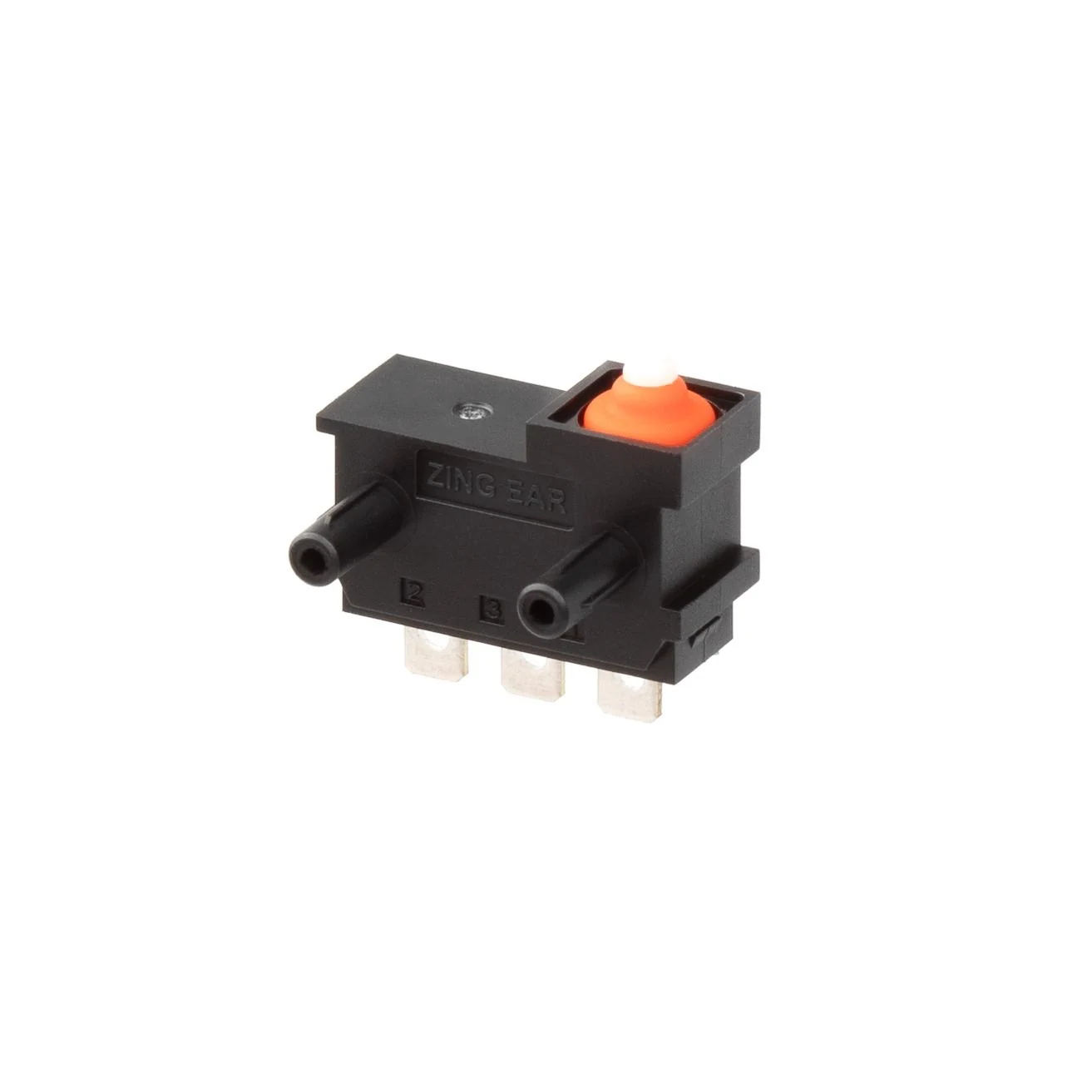
- Candidate: ZINGEAR G303-130K00A6, identified for a door-lock application.
- Published configuration: 12 VDC, 3 A, SPDT contact form and an IP67 ingress classification for the named variant.
- Acceptance evidence: The offered drawing and endurance-test conditions identify the part; an assembled-latch test establishes whether its transition point matches the door-state map.
The selected variant’s own datasheet and terminal drawing show its mounting and ingress limits. A standard package can simplify sourcing when its force, travel and lead exit fit the latch. A configured actuator or mount needs its own drawing and validation in the assembled latch.
The latch geometry, controller circuit and revision-specific test results determine whether this candidate remains suitable for the program.
Write a separate hood brief
A hood position switch may report a closure state to the body controller or theft-alarm system. The hood switch’s mounting, water exposure, service access, and failure consequence can differ substantially from a side-door latch. The hood-warning behavior comes from the vehicle program’s applicable requirements and controller design.
For the hood, define the desired state at primary and secondary latch positions, any separate bonnet-open alarm logic, the electrical input circuit, available cam travel, environmental exposure, and expected service life. The required number of distinct states determines whether one switch is sufficient. If the vehicle platform has another applicable requirement or customer specification, evaluate it on its own terms. A shared supplier and a similar sealed switch are possible, but the validation files should remain position-specific.
A datasheet has a narrow limit
An IP67-marked switch can still give an unreliable door signal if water reaches a lead exit in the latch module or the cam barely touches the actuator at one tolerance extreme. The switch report describes the tested enclosure; the vehicle program tests the assembled latch, controller signal and warning behavior under its chosen temperature, water, vibration and cycle conditions. FMVSS 206 addresses the applicable door-system requirements.
The most useful supplier response shows what was tested on the offered revision and where the configuration may change. Production-representative force and travel measurements reveal the switch range; worst-case latch and switch tolerance stacks show whether the state transition still occurs at the right point. The passing drawing revision ties that result to the component proposed for production.
Describing the door or hood position in an RFQ
Use a separate package for each door or hood position:
| Vehicle-program input | Supplier return | Vehicle-program check |
|---|---|---|
| Latch-state diagram, cam travel, mounting envelope and controller circuit | Exact part drawing, contact-state data and terminal/lead options | Match transition and fault behavior to the position truth table |
| Expected cycles, temperature/water exposure and desired failure response | Endurance and environmental test conditions plus sample plan | Test the assembled latch and harness across tolerance extremes |
| Production volume and approved revision controls | Control plan, change-notification process and lot traceability | Keep door and hood validation records position-specific |
ZINGEAR's configured micro switch development covers travel, operating force, terminal and actuator choices. For a door or hood application, our team can review an early mechanism drawing, the latch movement and the intended controller signal with you. The discussion can establish a candidate configuration and the assembled-latch checks for the vehicle program's approval process.
FAQ About Door-Ajar and Hood Position Switches
How can I source a micro switch for vehicle door-ajar or hood position sensing?
Begin with separate door and hood state maps, then compare each candidate’s operating and release points, contact circuit and exposure with the mounted mechanism. ZINGEAR G303-130K00A6 is a published door-lock starting candidate. A hood position needs its own geometry and environmental test.
Can one contact distinguish open, secondary-latched and fully latched?
A single transition reports two states. Distinguishing open, secondary-latched and fully latched positions requires another signal or suitable mechanical logic.
Does FMVSS 206 approve the micro switch?
FMVSS 206 addresses applicable door-lock and retention systems and some warning provisions. The vehicle program evaluates the switch inside its door system; hood sensing follows the program’s separate requirements.
Is IP67 enough to qualify the installed latch sensor?
IP67 describes the tested enclosure. The assembled latch also needs signal, lead-exit, tolerance and environmental checks for its actual mounting.
What changes when a door switch is considered for a hood?
The cam travel, mounting, water path, controller logic and warning behavior may all differ. A hood-specific drawing and test plan establish whether the same part can be reused.
Related reading: For a broader door and hood sourcing discussion beyond this US door-state brief, see our door-ajar and hood position switch guide.
Sources
Related Recommendations
-
ZINGEAR Micro Switch OEM Manufacturing Complete Guide
2026-07-23 -
ZINGEAR G306-150S150AA Automotive Micro Switch Officially Partners with Changan Automobile to Enable Precise Control of Sun Visors and Vanity Mirrors
2026-08-07 -
ZINGEAR G304 Micro Switch Debuts in Rail Transit Sector, Enabling Precise Sensing and Reliable Control for High-Speed Train Lifting Doors
2026-08-13 -
ZINGEAR G306-150E65BA-400 Electric Motorcycle Handbrake Micro Switch | Dreame Shouqu Certified Sensing Switch
2026-08-18 -
ZINGEAR G304 Micro Switch Supports Electric Two-Wheeler Electronic Lock Systems, Empowering Smart Lock Security and Durability Upgrade
2026-08-21 -
zingear Micro Switch Solution for Communication Base Station Equipment Status Detection — Building a Solid Safety Line for Long-term Stable Operation of Base Stations
2026-08-11 -
Electrolux Range Hood Switch Solution — Zing EAR: Solve Extreme Kitchen Reliability with Precision Sensing
2026-08-25 -
How can I replace the push-button switch on my range hood?
2026-08-27