
"G3 Series Micro Switch Dimension and Mounting Hole Guide (Including 2D/3D Drawings)"
1. Why Dimension Drawings Are Important
When selecting a micro switch, accurate dimension drawings are crucial for mechanical design and PCB layout. The G3 series micro switches feature a compact structure, widely used in space-constrained applications such as automotive door locks, electric push doors, and industrial control systems.
(1) Dimension drawings ensure:
(2) Precise alignment between the switch and installation location
(3) Proper actuator travel design
(4) Avoidance of installation interference or unstable mounting
(5) Correct implementation of waterproof sealing
2. Main Models Dimensions and Mounting Structures
Model | Product Name | Mounting Structure | Dimensions L×W (mm) | Mounting Holes | Features |
Ultra-compact waterproof /dustproof micro switch | A2 left positioning post | 13.3 × 5.3 | 2-Ø2.60 | Prevents rotation, ensures accurate actuation, suitable for outdoor waterproof devices | |
Micro switch replacement | Customizable | 13.1 × 8.0 | 2-Ø2.95 | Supports roller/lever/button actuators, ideal for device repair or replacement | |
High-precision long-life trigger switch | PCB pins | 12.25 × 5.0 | 2-Ø2.20 ±0.1 | Suitable for automated soldering, robots, and production lines | |
Automotive micro switch | A2 non-positioning post | 10.7 × 5.3 | Shell clip / bracket fixing | Modular installation, space-saving, vibration-resistant design | |
High-precision micro switch | PCB pins | 16.3 × 5.1 | 2-Ø4.53 | Suitable for home appliances, mechanical and electrical life up to 300,000 cycles |
Click the model to visit the official website for detailed specifications.
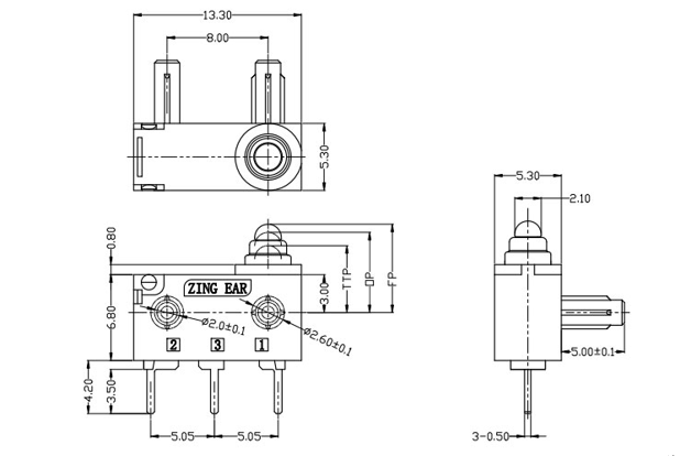
G303-130P00A53 Drawing
3. Terminal Types and Soldering Requirements
Terminal Type | Soldering Method | Process Requirements |
Tab type | Hand soldering | ≤350°C, ≤3 seconds |
PCB pins | Wave soldering | Preheat 100–130°C, solder 260°C ±5°C, 3–5 seconds |
Pre-wired | No soldering | Direct connector connection |
Excessive soldering temperature or time may damage internal contacts.
4. Installation Guidelines
To ensure reliable operation of the G3 Series IP67 waterproof micro switch, follow these installation recommendations:
Correct Actuation Direction
The G3 micro switch uses an angled push structure. Ensure the actuator presses vertically along the button axis.
Incorrect: Side pressing → may deform internal contacts, reducing lifespan
Correct: Press along the center axis to ensure stable switch operation
Actuation Travel Control
Pressing travel should reach 70–80% of the total travel:
Insufficient travel → contacts may not engage reliably
Excessive travel → may damage the housing or internal spring
Waterproof Sealing (IP67)
To maintain IP67 waterproof and dustproof performance:
Install on a flat surface, avoid bumps or recesses affecting the seal
Use sealing gaskets or sealant if necessary
Seal the cable outlet to prevent water ingress along wires
5. How to Obtain 2D/3D Drawings
G3 series provides:
2D Engineering Drawings (DWG/PDF): dimensions, tolerances, mounting hole coordinates, terminal dimensions
3D CAD Models (STEP/IGES): directly importable into design software
Acquisition methods: Download from the official ZINGEAR website, contact sales engineers, or apply online.
6. Technical Support and Sample Services
Free 2D/3D drawings download
Installation guidance
Sample requests (physical verification)
Custom development (terminals, wiring, actuation force)
[Click here for support and samples]
7. FAQ
Q1: What is the operating force of G3 micro switches?
A1: Standard models have 180g operating force, with clear tactile feedback and anti-misoperation. Custom models can be adjusted according to the mechanical design.
Q2: What is the difference between positioning and non-positioning posts?
A2: Positioning posts prevent rotation and ensure accurate actuation; non-positioning posts are suitable for modular installation and save space.
Q3: Can IP67 waterproof micro switches be submerged for long periods?
A3: No. IP67 guarantees short-term immersion (1m deep, 30 minutes). Long-term immersion may cause failure.
Q4: Can PCB pin terminals be hand-soldered?
A4: Not recommended. PCB pins are suitable for wave soldering. Hand soldering may cause unstable connections or damage internal contacts.
Q5: How to get complete 2D/3D drawings?
A5: Download from the official website, contact a sales engineer, or apply online for DWG/PDF and STEP/IGES files.
Tags: micro switch size diagram IP67 waterproof micro switch automotive micro switch micro switch drawing download ZINGEAR micro switch size diagram
Related Recommendations
-
Differentiated Competitiveness of 12 volt Micro Switch
2026-03-31 -
Can my brand logo be printed on the micro switch? ZINGEAR micro switch supports customization
2026-02-12 -
The differences between Micro Switch and Limit Switch
2026-02-12 -
Which brand of mouse micro switches is the best? Deep analysis and recommendation
2026-02-12 -
The Robust G9 Waterproof Micro Switch: Design, Applications and Manufacturing Excellence by ZING EAR
2026-01-13 -
G201 Sealed Micro Switch | ZING EAR China ODM & OEM Manufacturer
2026-01-13